

System for inspecting/transferring stud bolt material
A simple system configuration to reduce the cycle time by 44%
System Overview
1. Explanation of Process
Material, round bars, are checked for outer diameter before rolling. Acceptable bars are placed on the conveyor while unacceptable ones are put in the box collection.
2. Explanation of Operation
The circled values in the figure represent the sequence of operations.
- The feeding unit* raises one material bar from the stocker, the Z-axis air cylinder comes down, and the round bar is received by the air chuck.
- After the Z-axis air cylinder rises, the outer diameter of the round bar is inspected by the measurement sensor. After the inspection, the measurement sensor retreats through the operation of the sensor-retreating air cylinder.
- Based on the inspection result, the round bar is judged reject or qualify.
Reject: The round bar moves towards the conveyor and stops above the conveyor through the operation of the Y-axis air cylinder. Thereafter, the Z-axis air cylinder comes down and places the acceptable bar onto the conveyor.
Qualify: After the intermediate-stop air cylinder moves forward, the round bar moves to the intermediate-stop position through the operation of the Y-axis air cylinder. Thereafter, the Z-axis air cylinder comes down and puts the unacceptable bar into the collection box.
* Feeding unit: In general, a feeding unit separates the parts, etc., that are flowing continuously on the line, into individual parts.
In this example, the feeding unit raises each round bar (material) so that it can be grabbed by the air chuck.
Problems Experienced While Using the Air Cylinder
The outer-diameter inspection takes 1.0 second after the Z-axis air cylinder completes moving to the top position.
Increasing the speed at which the Z-axis air cylinder rises shortens the travel time, but vibration occurs when the cylinder stops.
Increasing the speed at which the Z-axis air cylinder rises shortens the travel time, but vibration occurs when the cylinder stops.
The same goes with the Y-axis air cylinder, and this cylinder was operated at low speed to prevent vibration.
The cycle time for transferring an acceptable bar was 9.0 seconds, and the system operated 15 hours a day.
Improvements Achieved by the ROBO Cylinder
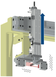
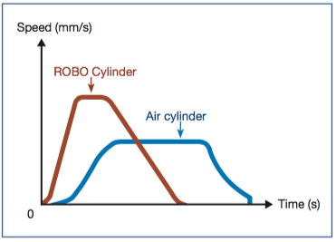
1. Setting desired speed, acceleration, and deceleration to achieve high-speed, vibration-free operations
The Y-axis and Z-axis air cylinders were changed to ROBO Cylinders.
The ROBO Cylinder lets you set desired speed, acceleration, and deceleration.
By setting the speed and acceleration high and the deceleration gradual, high-speed, vibration-free movements became possible.
![]()
As a result, the cycle time was reduced by 2.2 seconds.
Reduced by 2.2 seconds
2. Improved inspection method led to a shorter cycle time
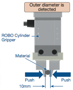
By using the push-motion operation and zone-signal output function of the ROBO Cylinder Gripper, the outer diameter of a round bar can be determined simply by allowing the ROBO Cylinder to grab the bar.
This eliminates the need for measurement sensor and sensor-retreating air cylinder.
The inspection time was reduced by 1.0 second.

Reduced by 1.0 seconds
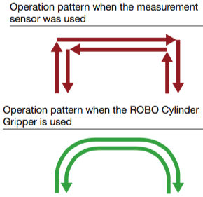
3. Arch-motion operation to achieve the shortest moving path
The system no longer needs to stop for inspection.
As a result, arch-motion operation is now possible using the Y-axis and Z-axis.
With the arch-motion operation, the ROBO Cylinder can move along the shortest path.
The ROBO Cylinder can be set up with ease using a teaching pendant.
![]()
As a result, the cycle time was reduced by 0.8 seconds.
Reduced by 0.8 seconds
Cycle time
| Air cylinder | ROBO Cylinder | |
| 9.0 seconds | 5.0 seconds | Total: |
| Point 1: 2.2 seconds Point 2: 1.0 second Point 3: 0.8 seconds |
4.0 seconds |
Cost Cutting Effect
1. Conditions
Required production quantity (day) |
6,000 pieces/day |
Labor cost (hour) |
$18 |
Annual operating days |
250 days |
2. Comparison of Air Cylinder and ROBO Cylinder
| Item | System using air cylinder | System using ROBO Cylinder | |
| Cycle time | 9.0 seconds | 5.0 seconds | |
| Line operating hours (day) | 15.0 hours/day 9.0 seconds x 6,000 pieces = 54,000 seconds = 15.0 hours |
8.3 hours/day 5.0 seconds x 6,000 pieces = 30,000 seconds ≒ 8.3 hours |
|
| Labor cost (annual) | $33,750* 15.0 hours x $9 x 250 days = $33,750 |
$13,800* 8.3 hours x $9 x 250 days = $18,675 |
|
Note: One operator oversees two systems, so the labor cost per hour is calculated as $18 / 2 systems = $9.
3. Cost Cutting Effect
| Air cylinder | ROBO Cylinder | ||
| Labor Cost (annual) | $33,750 – | $18,675 = | $15,075 |
| Difference = | $15,075 |
Result
By adopting the ROBO Cylinder, a simple system confi guration was achieved, and the cycle time decreased by 44%. $15,075 of annual cost savings was achieved.
* Exchange Rate: 1(USD) = 100(Japanese Yen)